Introduction
In the world of micro-drive systems—specifically for applications running on 1V to 30V and under 100W—choosing the right gear motor involves much more than simply checking the RPM and Torque on a datasheet. A single wrong decision in the early design phase often leads to late-stage problems like poor efficiency, excessive heat, or a motor lifespan that is too short for the product’s intended use.
When engineers face the selection process, they usually run into several key questions: Why are some motors significantly more expensive despite being the same size? Why does a stepper motor lose its strength at higher speeds? And in precision tasks, how much “lost motion” will the gearbox backlash actually cause?
This guide is designed to provide a technical deep-dive into the four most common drive technologies: Coreless, Cored, Stepper, and Servo gear motors. We will go beyond basic specifications and look at the underlying physics of each design. We will discuss how winding techniques, magnetic field distribution, and driver complexity affect both the performance of your machine and your total project budget.
Whether you are developing a handheld medical device, a high-precision optical instrument, or a consumer-grade smart lock, this guide will help you understand the trade-offs of each technology. Our goal is to provide a clear, professional reference to help you find the best balance between performance and cost.
Chapter 1: Coreless Motors — High Performance through Innovative Design
The Coreless DC Motor is often the first choice for high-end applications like medical devices and precision robotics. The main difference between this and a standard motor is exactly what the name suggests: it has no iron core in the center of the rotor.
1.1 Why are Coreless Motors so Expensive?
When engineers first look at the price of a coreless motor, they often wonder why it costs significantly more than a cored motor. The high price is not about branding; it is about the difficulty of manufacturing and the quality of the materials required.
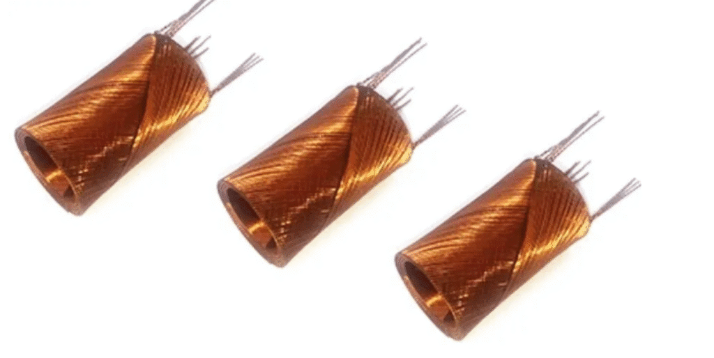
- The Self-Bonding Coil: In a normal motor, copper wire is wrapped around an iron frame. In a coreless motor, the copper wire is wound into a “cup” or “basket” shape that must support its own weight. This requires self-bonding wire—a special type of wire that sticks to itself when heated. Winding these wires into a perfect, balanced cylinder without an internal frame requires extremely high-precision machines. Even a tiny error in the winding will cause the motor to vibrate and fail at high speeds.
- Premium Magnet Materials: Because there is no iron core to help focus the magnetic field, a coreless motor must use much stronger magnets to achieve the same power. We typically use high-grade Neodymium magnets (such as N45 or N52). These rare-earth materials are extremely much more expensive than magnet strip that common DC cored motors use.
- Tight Manufacturing Tolerances: Because the gap between the rotating coil and the stationary magnets is very small, every part must be machined to a very high level of accuracy. This increases the production time and the cost of quality control.
1.2 The Technical Advantages: Low Inertia and No Cogging
Removing the iron core changes the physics of how the motor moves. This results in two major performance benefits:
- Low Inertia (Fast Response): Inertia is a measurement of how hard it is to start or stop an object. Because the coreless rotor is made only of copper wire (which is much lighter than iron), it has very low inertia. This allows the motor to accelerate or stop almost instantly. In technical terms, the “mechanical time constant” is very low.
- No Cogging Torque: Since there are no iron “teeth” in the rotor, there is nothing for the magnets to grab onto as the motor turns. This eliminates Cogging Torque. The result is a perfectly smooth rotation, even at very low speeds. This makes coreless motors ideal for applications that require steady movement, such as high-resolution optical scanning.
1.3 The Thermal Limitation
While coreless motors are efficient, they have one weakness: heat management. In a standard motor, the iron core helps pull heat away from the copper wires. In a coreless design, the wires are “standing alone.” If the motor is overloaded or stalled, the heat builds up very quickly in the wires and can melt the adhesive that holds the coil together.
Because of this, coreless motors are not suitable for applications that need long periods of overloading or high-torque stalling.
Advantages and Disadvantages: A Root-Cause Analysis
| Advantage | Physical Root Cause | Engineering Benefit |
| Low Inertia | No iron core ($J$ is minimized) | Start/Stop cycles in <5ms. Perfect for high-speed pick-and-place. |
| High Efficiency | No Eddy Current or Hysteresis losses in the rotor | Efficiency up to 90%+. Extends battery life in portable medical devices. |
| Linearity | Proportional relationship between voltage/speed and torque/current | Simplifies control loops; predictable performance. |
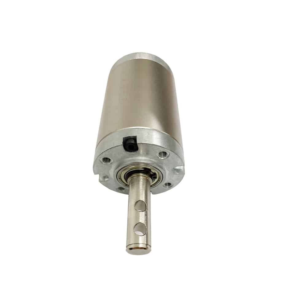
Chapter 2: The Gearbox – Converting High Speed into Useful Torque
A coreless motor is designed to operate typically between 6,000 and 15,000 RPM. However, in most practical applications—such as moving a camera lens or a robotic arm—this speed is too high, and the motor’s direct torque is too low to move the load.
To fix this, we use a Planetary Gearbox. The gearbox performs two main jobs:
- It reduces the motor’s high rotation speed to a low RPM.
- It increases the torque so the motor can handle heavier load.
2.1 Understanding Backlash: The Problem of “Lost Motion”
When you add a gearbox to a motor, you must deal with a technical issue called Backlash. If the gearbox design is poor, it will ruin the precision of your coreless motor.
What is Backlash?
Backlash is simply the tiny gap between the teeth of the gears. In a standard gearbox, these gaps are usually there to stop the gears from jamming or getting too hot.
However, in precision work, this gap causes “Lost Motion.” For example, if the motor stops or changes direction, the output shaft does not move immediately because it has to travel across that tiny gap first. This results in positioning errors and makes the system feel “loose.”
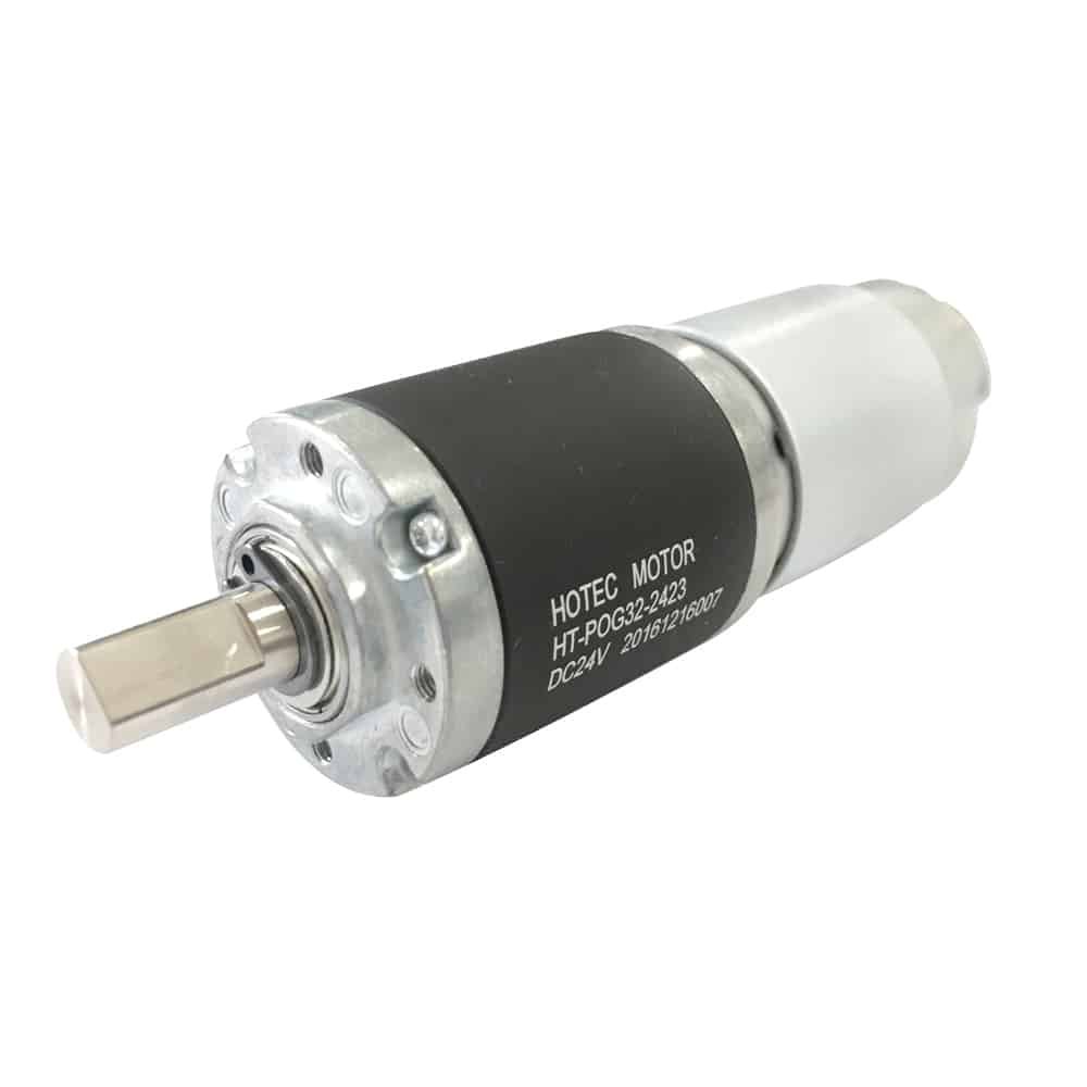
How HOTEC MOTOR Solves This?
At HOTEC MOTOR, we use specific engineering methods to minimize these gaps without causing the motor to work too hard:
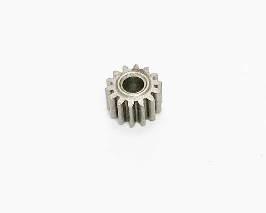
- Adjusting the Pitch Diameter: We manufacture gears with slightly larger “pitch diameters” (the effective size of the gear teeth). By carefully matching the sun gear and the planet gears, we ensure the teeth fit together snugly. This removes the gap while keeping the rotation smooth.
- Precision Tolerances: By controlling the manufacturing of every tooth, we reduce the backlash.
The result: When the motor moves, the gearbox moves instantly. There is no “play” or “slop” in the system, which is essential for any application that requires exact positioning.
Chapter 3: Cored DC Motors — The Reliable Industrial Standard
The Cored DC Motor is the most common motor design used in industrial and consumer products today. You will find these motors in everything from automotive seat adjusters to basic household appliances. It is a reliable choice for projects that require a balance of power and affordability.
3.1 The Iron Core and the Use of Ferrite Magnets
A cored motor gets its name from the center part of the motor (the rotor), which consists of a stack of thin steel sheets called laminations. The copper wire is wound around these steel teeth.
In the motor industry, these are frequently called Ferrite Motors. This name comes from the specific way the iron core allows us to use lower-cost materials.
Why it is the Lowest Cost Option
The main reason cored motors are the most affordable choice is the relationship between the iron core and the magnets:
- Magnetic Concentration: Iron is very good at conducting magnetic force. Because the iron core helps focus the magnetic field, the motor does not need expensive, high-strength magnets.
- Ferrite Magnets: Instead of using expensive rare-earth magnets like Neodymium, cored motors use Ferrite magnets. Ferrite is a ceramic material that is much cheaper to produce and easier to source.
When you combine an iron core with Ferrite magnets, you get a motor that is much less expensive to manufacture than a coreless motor. This makes it the best option for high-volume production where keeping the unit cost low is the priority.
3.2 The Trade-off: Understanding Cogging Torque
While cored motors are cost-effective, the iron core creates a specific mechanical effect known as Cogging Torque.
What causes Cogging?
If you turn the shaft of a cored motor by hand, you will feel a “notchy” or clicking sensation. This happens because the iron teeth on the rotor want to line up with the magnets inside the motor. As the rotor spins, it “jumps” from one magnetic position to the next rather than turning in one perfectly smooth motion.
How it affects your project
At high speeds, you generally will not notice cogging. However, at very low speeds, this jumping effect can cause small vibrations or uneven movement. If your application requires perfectly smooth motion at low RPM—such as a high-end camera stabilizer or a precision dosing pump—the vibration from a cored motor might be a problem. In those cases, a coreless motor (which has no cogging) would be a better choice.
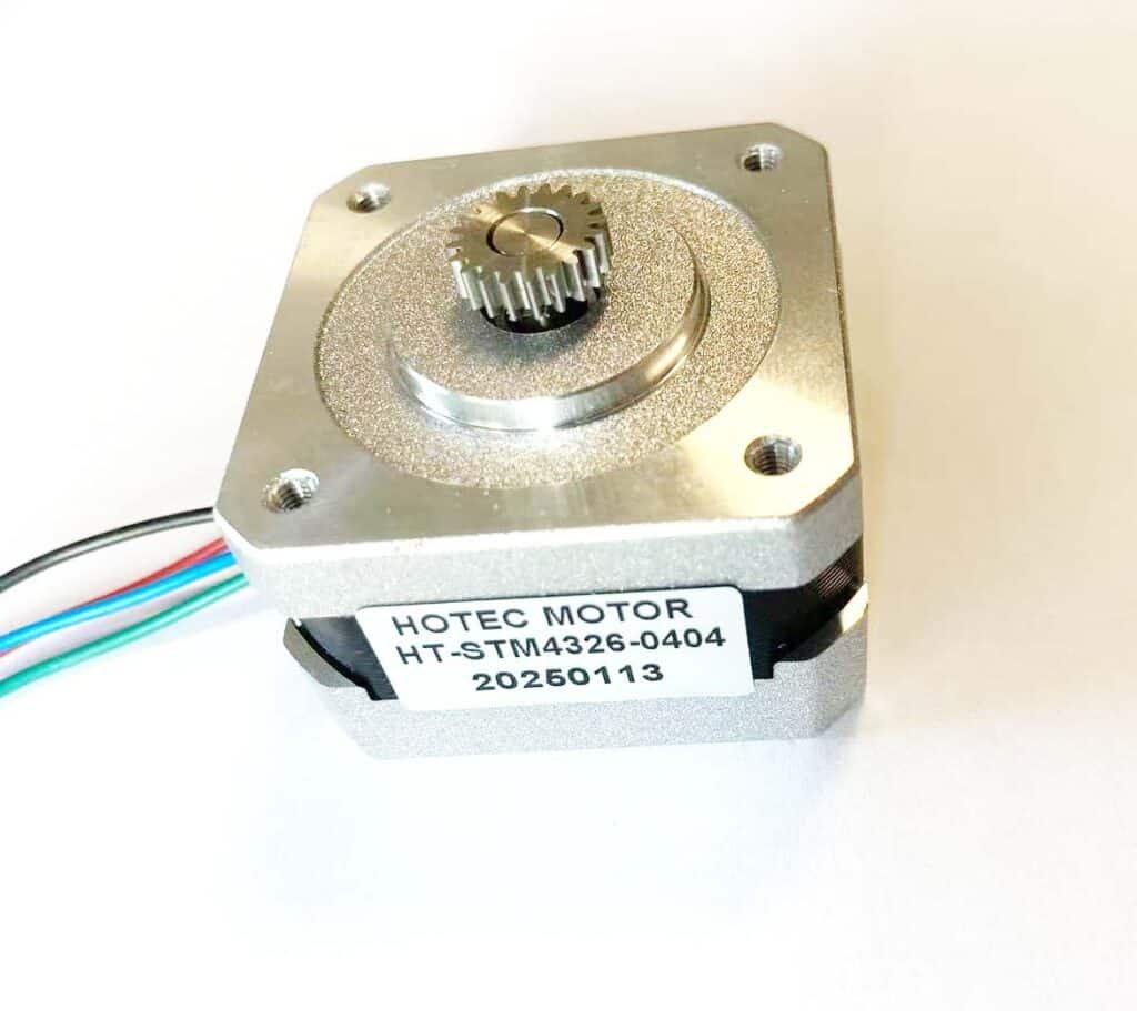
Chapter 4: Stepper Gear Motors — Precision and System Costs
A Stepper Motor operates differently than a standard DC motor. Instead of spinning continuously when power is applied, it moves in fixed increments called “steps.” Most micro stepper motors move 1.8 degrees per step.
The main advantage of this design is that you can track the motor’s exact position by counting the number of steps it has taken. This allows for precise positioning without the need for an expensive feedback sensor, such as an encoder.
4.1 Why Stepper Motors Require Gearboxes
While stepper motors are precise, they have specific physical characteristics that a gearbox helps improve:
- Increasing Resolution: For many applications, a 1.8-degree step is too large. By adding a gearbox with a 100:1 ratio, the output movement is reduced to 0.018 degrees per step. This provides extremely fine control for a relatively low cost.
- Controlling Vibration: Stepper motors have a tendency to vibrate or “ring” when they stop at a specific step. A gearbox provides mechanical resistance, which acts as a damper. This helps the motor settle into position faster and reduces the noise during operation.
4.2 Understanding High-Speed Torque Loss
Engineers should be aware that stepper motors lose torque as their speed increases. This is caused by Inductance.
Electricity takes a small amount of time to build up to full strength in the motor’s copper coils. When the motor spins at high speeds, the electrical pulses switch so fast that the current never reaches its full level before the next step begins. Because the current is lower, the torque drops significantly. For this reason, stepper gear motors are most effective in low-speed, high-precision tasks, such as 3D printing, medical dosing pumps, or automated valves.
4.3 The “Hidden” Cost: Motor vs. System Price
When comparing the price of a stepper motor to a cored motor, the motor units themselves often cost nearly the same. However, the total cost of the system is usually much higher for a stepper motor due to the control electronics.
- Cored Motor Drivers: These are simple and inexpensive. A cored motor can often be controlled with a basic H-bridge circuit or, in some cases, connected directly to a power source.
- Stepper Motor Drivers: A stepper motor cannot function without a Specialized Stepper Driver. This device must precisely manage the timing and the sequence of electrical pulses sent to the motor. These drivers are complex and are often more expensive than the motor itself.
The Bottom Line: If your project has a very tight budget, a cored motor is the more economical choice because the driver is much cheaper. A stepper motor system is an investment that should only be chosen when your application requires exact, step-by-step positioning.
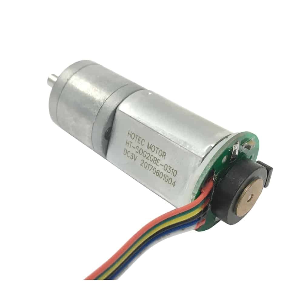
Chapter 5: Servo Gear Motors — High-Precision Closed-Loop Systems
It is important to recognize that a Servo is not a specific type of motor. Instead, it is a closed-loop system. A complete servo gear motor system consists of four main parts: a motor (which can be cored or coreless), a gearbox, a feedback sensor (encoder), and a controller.
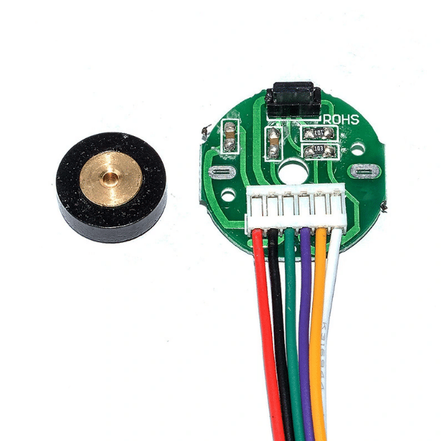
5.1 The Role of the Encoder and Feedback
In a standard motor system, the controller sends power to the motor but has no way to verify if the motor reached the target position. In a Servo system, the Encoder acts as a feedback sensor that reports the motor’s exact position to the controller every millisecond.
The precision of this system depends on the Encoder Resolution, which is measured in PPR (Pulses Per Revolution):
- Low-Resolution (3–7 PPR): These usually use simple magnetic Hall-effect sensors. They are effective for monitoring rotation speed or direction, but they do not provide enough data for exact positioning.
- High-Resolution (512–1024+ PPR): These sensors allow the system to detect even a tiny fraction of a degree of movement. If the motor is pushed out of place or misses its target, the controller instantly detects the error and adjusts the electrical current to correct the position.
| Sensor Type | Resolution (PPR) | Pros | Cons |
| Hall Effect (Magnetic) | 3 – 1024 | Robust, immune to dust/oil, compact. | Lower precision, sensitive to external magnetic fields. |
| Optical Encoder | 500 – 10,000+ | Incredible precision, zero magnetic interference. | Fragile (glass disks), sensitive to dust/moisture. |
5.2 Why Choose a Servo Gear Motor other than stepper motor?
Servo systems are the most expensive drive option, but they provide the highest level of performance. They offer several key advantages over other motor types:
- High Speed and Precision: They combine the high-speed capabilities of a DC motor with the precise positioning of a stepper motor.
- Constant Torque: Unlike stepper motors, which lose torque as they spin faster, servo motors maintain high torque throughout their speed range.
- Self-Correction: Because of the closed-loop feedback, the system can compensate for unexpected changes in load or resistance.
Due to these features, servo gear motors are the industry standard for high-end applications such as robotic arms, 5D cinema and precision medical surgical equipment.
The Final Selection Matrix: Which Motor is Right for You?
To help you decide, here is a quick comparison of the four technologies based on 1V-30V micro-drive requirements:
| Feature | Cored DC Motor | Coreless Motor | Stepper Motor | Servo System |
| System Cost | Lowest (Cheap Driver) | Medium-High | Medium-High (Expensive Driver) | Highest |
| Precision | Low | Low (unless Servo) | High | Very High |
| Efficiency | Medium (30%~65%) | High (~90%) | Low | High |
| Lifespan | Medium | Medium-High | High | Very High (if BLDC) |
| Best For: | Budget projects, locks, toys. | Handheld medical tools, drones. | Precision pumps, 3D printers. | Robotics, high-end automation. |
Conclusion: Making the Right Choice for Your Application
Choosing the right micro gear motor is a balance between performance requirements and total system cost.
- If you need a simple, low-cost solution, the Cored DC Motor is your best bet.
- If you need ultra-fast response and high efficiency in a small package, choose a Coreless Motor.
- If you need exact positioning at low speeds without an encoder, the Stepper Motor is the right tool, provided you budget for the driver.
- For the absolute highest precision and reliability, a Servo System is the professional choice.
At HOTEC MOTOR, we provide the engineering expertise to help you match these technologies to your specific project needs. Whether you need a custom gear ratio or advice on encoder resolution, our team is here to ensure your motion control is perfect.
Ready to Find the Perfect Motor for Your Project?
Choosing between a coreless, cored, stepper, or servo motor is a big decision that affects your product’s performance and your total budget. As we’ve discussed, there isn’t a “one-size-fits-all” answer—it all depends on your specific needs for torque, speed, and precision.
At HOTEC MOTOR, we help you engineer the right movement. Our team specializes in the 1V to 30V range micro ferrite motors with gearbox, and we have the experience to help you with motor selection.
How We Can Help You:
If you are currently in the design phase, the best way to move forward is to talk through your requirements with an expert. To give you the most accurate recommendation, it helps if you can provide a few details:
- The Voltage and Target RPM you need at the output shaft.
- The Torque load your application will handle.
- Size constraints (how much space do we have to work with?).
- Budget goals for the total motor and driver system.
Whether you need a custom gear ratio for a coreless medical tool or a high-volume supply of reliable cored motors for a smart lock, we are here to provide the technical support you need.
Get a Technical Consultation Today
Don’t leave your motor selection to chance. Contact our engineering team today to discuss your project. We can provide CAD drawings, torque-speed curves, and sample units to help you get your project moving in the right direction.